Progress on an Amp
I was looking for a 4-channel amp to drive a pair of bipole speakers. For fun, I decided to try to build one. I bought a broken amp off eBay just for the case for about $30. In retrospect, I probably should have bought an inexpensive blank case they sell to hobbyists. At the time, I was intimidated by drilling and tapping a lot of holes in a metal case. Since then, I have found this to be easy, easier in fact that ripping all the guts out of the old amp.
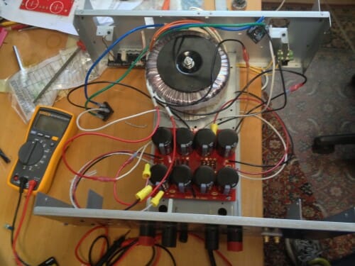
Anyway, I finished the power supply. The big fat over-sized torroid delivers 35 volts AC to the diode bridges and the smoothing capacitors on the back end, which in turn delivers about 48.5 volts DC for my amp (this measured dead-on the expected 35*sqrt(2)-1 one would expect). I tried to save some of the old amp's 110V circuitry (such as some filter capacitors). It had a relay with some sort of delay circuit in parallel with a big resistor as a soft-start mechanism, to prevent a big inrush current. I could never make it work right, so I replaced it with the poor man's alternative, which is a couple of thermistors that have high resistance cold but quickly heat up and lose their resistance when the power is on.
The capacitors and RC network are in an absolutely beautiful empty board I bought from someone on eBay who etched boards for First Watt kits (an amp series that the designer has generally put into the public domain). I cribbed the power supply off the design for an F5 amp, though I had to adjust wattage and voltage values to match the voltage I needed. I spent a week dithering on what capacitors to use -- audiophiles go on an on about capacitors. Finally, though I am sure all these folks will swear to God they can hear the difference between two brands of capacitor in the power supply, I finally decided I probably would not notice and bought some well-regarded but reasonably priced ones (similar to my approach on that other audio equivalent of wine-snobbery, speaker cables).
What you don't see are two big aluminum heat sinks, which will fill much of the space on either side of the power supply. The diode bridges and amps will be connected to these. I have circuits both for a Class A amp, which will need every inch of the cooling, and a class D amp, for which the heat sinks will be an unnecessary overkill. But they came with the box and I have the space.
Why? -- Because he can!
I trained as an EE, and (back in college days) built my own speakers, etc.. Today, after too many decades away from actual practice, I would be reluctant to try something like this.
Color me impressed.
great stuff warren! I dont usually get into this aspect of stuff, too much work to do elsewhere :) one day I'll get around to replacing all of the caps on my old HK Chorale!
"I am sure all these folks will swear to God they can hear the difference between two brands of capacitor in the power supply"
Right up until someone does an A/B test.
Althouse.com very recently referenced an excellent article pointing at the absurdity of writers describing wines after tasting them. Likewise some of the hoo-hah about sound systems. I remember the ad for the $100 2-meter long power cord. By the time that many of us can afford upper end sound systems, our hearing has been affected to the point that we can no longer tell the difference between A and B, if we ever could.
Nice one Warren. I never knew you had it in you. You should be pleased with the first watt. It's not so hard to tell different capacitors when they are directly in the signal path, but in the power supply? This all depends on how it's designed and implemented. Not impossible, but not a slam-dunk. (ps I designed the Moskido class A amp which is another popular diy amp, or was when I maintained an interest in it).